


What is a transistor? Structure, principles and practical applications
01-10-2025 1.359
Transistor is a key semiconductor component commonly used as an amplifier or an electronic switch. To better understand the overview of what a Transistor is, let’s find out with Intech Group in the following article:
What is a Transistor?
A transistor is a key semiconductor component in electronics, used to amplify or switch electrical signals. The basic structure of a transistor consists of three semiconductor layers joined together in the form of NPN or PNP. Thanks to its ability to control current, transistors have become the foundation for most modern electronic devices such as microprocessors, audio amplifiers, power supplies and integrated circuits (ICs).
Without transistors, you would have no smartphones, no Internet, no computers…

Structure of a Transistor
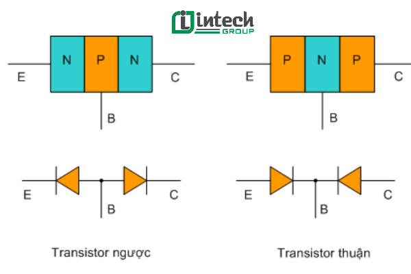
A transistor is a semiconductor component consisting of three semiconductor layers joined together, forming two P-N junctions. Based on the order of semiconductor layers, transistors are divided into two types:
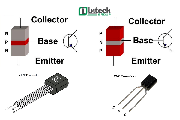
- NPN Transistor: Consists of two N-type semiconductor layers sandwiched between a P-type layer.
- PNP Transistor: Consists of two P-type semiconductor layers sandwiched between an N-type layer.
Structurally, transistors can be seen as two diodes connected in opposite directions, but they operate completely differently thanks to the control of the middle leg (Base).
The three terminals of the transistor include:
| Peak | Symbol | Functional description |
| Base | B (Base) | Is the middle semiconductor layer, very thin and has a low concentration of impurities. Controls the current. |
| Emitter | E (Emitter) | Provides the main current for the transistor. Has a high concentration of impurities to increase the ability to emit current. |
| Collector | C (Collector) | Collects current from the Emitter. Has a large cross-section to dissipate heat and pass current effectively. |
Although the Emitter and Collector use the same type of semiconductor (N or P), they cannot be interchanged due to differences in size and concentration of impurities. Incorrect installation will cause the transistor to not function properly.
Transistor symbols and shapes
On the market today, transistors are manufactured by many countries with a variety of component codes and symbols. However, the most popular are transistors from Japan, the US and China. Here is how to identify and classify them based on their code:
1. Japanese Transistor
Japanese transistors usually have code numbers starting with A, B, C, D:
| Beginning Symbol | Transistor Type | Characteristics |
| A…, B… | PNP (Forward Transistor) | Higher power, lower operating frequency |
| C…, D… | NPN (Reverse Transistor) | Usually used in high-frequency, low-power circuits |
For example: A564, B733 (PNP); C828, D1555 (NPN)
2. American Transistor
Transistors manufactured in the US often have symbols starting with 2N, according to JEDEC (Joint Electron Device Engineering Council) standards: Common examples: 2N3055 (High-power Transistor), 2N2222 (Fast Signal Transistor)
Note: The code “2N…” is often common in international technical documents.
3. Chinese Transistor
Chinese-made transistors have a format that starts with the number 3, followed by two letters and a sequence of numbers:
- First letter: Identify the transistor type
- A, B: PNP (Forward-looking transistor)
- C, D: NPN (Reverse-looking transistor)
Second letter: Identify the operating frequency range
- X, P: For audio frequency (AF) circuits
- A, G: For high frequency (RF) circuits
Example:
- 3CP25 → NPN, used in audio frequency circuits
- 3AP20 → PNP, used in high frequency circuits
Understanding the correct transistor symbols not only helps to choose the right component for the circuit but also saves time looking up, especially when working with datasheets or replacement components. Always check the transistor type (NPN or PNP), power and frequency range to ensure the circuit operates stably.
How to identify the E, B, C pins of a Transistor simply and accurately
When using a Transistor, correctly identifying the Emitter (E), Base (B) and Collector (C) pins is very important to ensure the device operates effectively. Below are instructions on how to identify the Transistor pins for each type:
1. Identify the pins of a small power Transistor
With small power Transistors, the pin positions may vary depending on the country of manufacture:
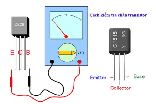
Transistors made in Japan (eg: C828, A564):
- Pin C (Collector) is in the middle
- Pin B (Base) is on the right
- Pin E (Emitter) is on the left
- Pin B (Base) is in the middle
- Pin C (Collector) is on the right
- Pin E (Emitter) is on the left
Note: Some counterfeit or unknown origin transistors may not follow the above convention. To ensure accurate determination, it is recommended to use the multimeter measurement method.
2. How to measure Transistor pins with a multimeter
Switch the meter to the x1 Ω scale
Hold one measuring stick fixed at any pin, the other stick touches the other two pins in turn
If the meter needle goes up evenly in both measurements, the fixed pin is the Base pin (B)
If the fixed stick is black, it is an NPN type Transistor (reverse)
If the fixed stick is red, it is a PNP type Transistor (forward)
3. Identify the pins of a large power Transistor
For large power Transistors (usually with a metal shell or large pins), the order of the pins usually follows the rule:
- Left: Pin B (Base)
- Middle: Pin C (Collector)
- Right: Pin E (Emitter)
Identifying the correct pins of the Transistor not only helps avoid errors when assembling the circuit but also protects other electronic components. Always check the datasheet or use a multimeter to ensure maximum accuracy.
Important technical parameters of Transistors
Transistors are semiconductor components commonly used in amplifier, control and switching circuits. To use them effectively, you need to understand the basic technical parameters and understand each type of specialized Transistor.
1. Basic technical parameters of Transistors
Maximum current (IC max): Is the maximum current that the Transistor can withstand at the Collector terminal. If this limit is exceeded, the Transistor will be overloaded and damaged.
Maximum voltage (VCE max): Is the maximum voltage placed between the Collector - Emitter terminals. Exceeding this value will cause the Transistor to be punctured and lose its function.
Cut-off frequency (fT): Is the maximum frequency at which the Transistor can effectively amplify the signal. If this frequency is exceeded, the amplification will be significantly reduced.
Current amplification factor (hFE or β): Is the ratio between the Collector current (IC) and the Base current (IB), indicating the amplification ability of the Transistor. For example: If hFE = 100, the IC current will be 100 times the IB current.
Maximum power (Pmax): Is the maximum power dissipation of the Transistor, calculated by the formula: P = VCE × IC. If the power exceeds the limit, the Transistor will heat up and burn out.
2. Some special types of Transistors and applications
Digital Transistor
Is a type of Transistor with a built-in limiting resistor at the Base pin (usually a few tens of kΩ), making it easy to control with logic signals such as 5V from a microcontroller. Often used in electronic switch circuits, digital logic circuits, and automatic device control circuits.
Identification symbols:
Prior type (PNP): DTA, KRA, RN22
Reverse type (NPN): DTC, KRC, RN12, KSR, UN…
Practical example: DTA132, DTC124
Instructions on how to check whether a transistor is alive or dead simply with a multimeter
A transistor is an important semiconductor component in electronic circuits. However, during operation, the transistor can be damaged due to high temperature, humidity, abnormal increase in power supply voltage or manufacturing errors. To determine whether the Transistor is still working or broken, you can apply the testing method with an analog multimeter, based on the equivalent structure of two semiconductor diodes inside the Transistor.
1. Principle of testing NPN Transistors
NPN Transistors can be tested similarly to two diodes with the same Anode pole, that is, the common point is the Base (B) pin.
How to measure: Place the black probe on pin B, the red probe on pin C and pin E respectively. If the meter shows the needle up (there is current), that means the two diodes are in the forward state. If measured in the opposite directions and the needle does not go up, the Transistor is working normally
2. Principle of testing PNP Transistors
PNP Transistors can be tested similarly to two diodes with the same Cathode pole, with the common point also being the Base (B) pin.
How to measure: Place the red probe on pin B, the black probe on pin C and pin E respectively. If the meter shows the needle up, that means the diodes are in the forward state. Other reverse measurement directions if the needle does not rise, it proves that the Transistor is still good.
3. How to identify a damaged Transistor
The needle does not rise when measuring in the forward direction from B → C or B → E: The Transistor is broken (BE or BC)
The needle rises in both directions between B ↔ C or B ↔ E: The Transistor is leaking or shorted inside
The needle rises between C ↔ E: The Transistor is shorted between CE, meaning it is seriously damaged
Notes when checking the Transistor
Use an analog multimeter at the x1 Ω scale
Make sure the Transistor has been removed from the circuit to avoid errors
If possible, look up the Transistor datasheet to know the exact pin diagram
Regularly checking the Transistor helps you detect problems in the circuit early and ensure the device operates stably and safely.

How does a Transistor work?
1. How does a NPN Transistor work
An NPN Transistor works as a switch that controls a large current at the Collector (C) terminal through a small current at the Base (B) terminal. To understand the principle, we consider the structure and how to power an NPN Transistor as follows:
Apply voltage UCE: (+) to the C terminal and (–) to the E terminal.
Apply voltage UBE: (+) to the B terminal and (–) to the E terminal, through a switch and current-limiting resistor.
Operation of an NPN Transistor:
When the switch is open: even though the UCE voltage is applied, there is no current flowing through the C-E terminal (IC = 0). The transistor is not conducting.
When the switch is closed: the UBE voltage biases the B-E junction forward, creating an IB current running from B → E. Immediately, a much stronger IC current appears from C → E, showing that the Transistor begins to conduct.
So it is clear that the IC current depends entirely on the IB current and depends according to a formula.
IC = β.IB
In which:
IC: Collector – Emitter current
IB: Base – Emitter current
β (hFE): Transistor current amplification factor
Explanation: When there is an IB current, because the semiconductor layer at the B pole is very thin and has little doping, most of the electrons from the E pole easily pass through the junction to the B pole. A small part forms an IB current, the rest is attracted to the C pole due to the UCE voltage creating an IC current.
2. Operating principle of PNP Transistor
PNP Transistor has the same operating principle as NPN, however the polarity of the power source and the direction of current are opposite.
How to supply power to PNP Transistor:
- Apply voltage UCE: (+) to E pole and (-) to C pole.
- Apply voltage UBE: (+) to E pole and (-) to B pole, through the switch and current limiting resistor.
- When the switch is open: no current flows from E to C (IC = 0), the Transistor does not conduct.
- When the switch is closed: the voltage UBE biases the B-E junction forward, creating a current IB from E → B. As soon as there is a current IB, a larger current IC will appear from E → C.
Similar to NPN:
IC = β.IB
In which IC goes from the E pole to the C pole, IB from E to B.
NPN transistor: current goes from Collector → Emitter, when there is a control current from Base → Emitter.
PNP transistor: current goes from Emitter → Collector, when there is a control current from Emitter → Base.
Conduction condition: must bias the BE junction forward with the voltage UBE, from which the Transistor will conduct the IC current.
Distinguishing NPN and PNP Transistors
| NPN Transistor | PNP Transistor | Structure |
| Structure | Includes 3 layers: N - P - N | Includes 3 layers: P – N – P |
| Direction of electric current | Current flows from Collector (C) to Emitter (E) | Current flows from Emitter (E) to Collector (C) |
| Operating conditions | The Base pin needs a positive voltage relative to the Emitter. | The Base pin needs a negative voltage relative to the Emitter. |
| Circuit diagram symbols | The arrow at the Emitter pin points outside the transistor. | The arrow at the Emitter pin points inside the transistor. |
| Control flow type | Positive current (in line with positive source circuit) | Negative current (suitable for circuits using negative power sources) |
| Popularity | Very common in modern electronic circuits | Less common, often used in special circuits |
| Common applications | Amplifier circuit, control, microcontroller, Arduino | Current inversion circuit, negative logic circuit, special power supply circuit |
| Tips to remember | “NPN: Not Pointing iN” – the arrow is not pointing to | “PNP: Pointing in Please” – arrow pointing inward |
Note: When designing a circuit, always check the pinout (B – C – E) of each transistor type as it may differ depending on the part number. Each type will be suitable for its own application and circuit type, so it is necessary to choose the right one to ensure stable operation.
Simple Circuit Creation Guide Using Transistor
You can start with a simple LED on/off circuit to get familiar with how an NPN transistor works. This is a basic but useful circuit for beginners in electronics.
1. Components needed
1 x NPN Transistor (common types: BC547, 2N2222)
1 x LED
1 x 330Ω resistor (limit current for LED)
1 x 10kΩ resistor (activate Base)
Breadboard, connecting wire, 5V DC power supply
2. Schematic diagram
Collector pin connected to the negative pin of LED
The positive pin of LED connected to 330Ω resistor, then connected to 5V positive power supply
Emitter pin connected directly to GND
Base pin connected to a 10kΩ resistor, then received control signal (can be push button, microcontroller or activation voltage)
3. Operating principle
When a voltage of about 0.7V is applied to the Base pin, the transistor conducts.
Current will flow from 5V source → LED → Collector → Emitter → GND → LED lights up.
When there is no voltage to the Base, the transistor is off → LED is off.
4. Notes when using
Make sure to connect the B – C – E pins of the transistor in the correct order (refer to the datasheet).
Do not supply more than the rated voltage to the transistor and LED.
Check the direction of the LED before supplying power.
Applications of Transistors in practice
Transistors are semiconductor components that play an extremely important role in modern electronic devices. Thanks to their ability to amplify signals and act as electronic switches, transistors have become indispensable components in analog and digital electronic circuits.
1. DC voltage amplification
Transistors are used in DC amplifier circuits to increase the signal level from sensors or input devices. In addition, it is also present in voltage regulator circuits, differential amplifier circuits and high-precision amplifier circuits.
2. AC voltage amplification
Transistors are used to amplify audio signals or carrier signals in audio equipment, radios and televisions. The amplified AC signal helps improve sound and image quality.
3. Power amplification
This is an important application in large audio systems, power amplifiers for speakers or high-power transmission systems. Transistors help increase both voltage and output current to control high-power devices.
4. Switching and switch control
Transistors act as electronic switches that turn on/off the current. In relay control circuits, microcontrollers or automation systems, transistors play a role in switching quickly and accurately. In particular, bipolar transistors (BJTs) can act as switches without the need for mechanical relays.
Transistors are the foundation of every modern electronic system. From simple household appliances to complex industrial systems, transistors contribute to efficient signal processing, control and amplification. Understanding the applications of transistors will help readers grasp the importance and practical applications of this component in life and electronic engineering. Intech Group is a leading provider of solutions for precision mechanics, automation, technology and energy in Vietnam. Contact us now for specific advice and support.